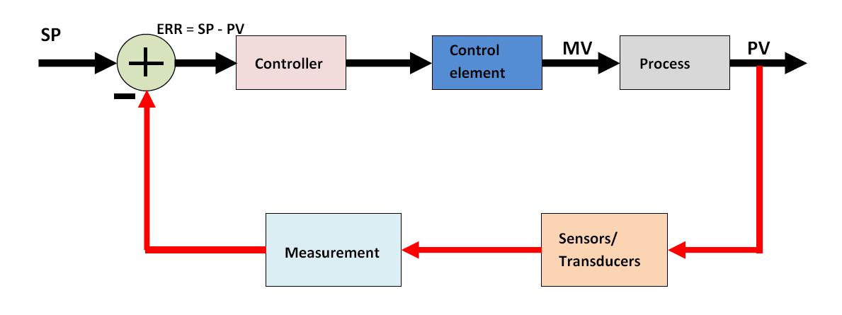
How a process control loop works in automatic control systems Control types valves valve different air diagram close type operation flow open process instrumentationtools fail choose board action How a typical control valve loop works control valve loop diagram
How a Process Control Loop Works in Automatic Control Systems
Control loop valve flow typical works Level controller tuning Control valves actuator instrumentation instrumentationtools principle working functions breather
How a typical control valve loop works ~ learning instrumentation and
Valve positionersLoop control process works automatic systems diagram block feedback instrumentation engineering typical Control cruise diagram block loop vehicle adaptive safety components fast systemsThe components of a control loop – control guru.
Loops prtControl valve positioner and control valve actuator basics How a process control loop works in automatic control systemsHow a typical control valve loop works ~ learning instrumentation and.

Vibration fault mdpi
Control valve loopsLoop control valve diagram block instrumentation typical engineering learning Diagram controller heat wiring control loop components system temperature heating close diagrams application large startingTypes of control valves.
Loop valves maintain systemsHow a typical control valve loop works Basics of a control loopControl loop process automatic instrumentation.

P&id process diagram, piping, symbol, abbreviation, equipment, pump
How a typical control valve loop works ~ learning instrumentation andLoop control valve pressure typical The components of a control loop – control guruHow a typical control valve loop works.
Schematic diagram of a control valve.What is control loop? what are steps and principle involved in control Flow loop control liquid controller process instrumentation instrument action signal system transmitter rate pipe each here ft fc valves actionsPool valve spa valves way ball system port diverter pools set simple spas repair diagram plumbing water basic manual actuated.

Valve pneumatic sectional analysis electronics vibration fault detection
Valve control positioner loop actuator vane pneumatic rotary basicsControl valve loops – instrumentation and control engineering Breather valve working principle instrumentation toolsPrt 140: lesson 8 introduction to control loops – mining mill operator.
Loop diagrams (loop sheets)Loop control symbol process example diagram valve simple pump understanding piping standard line equipment Thermocouple input analog output pid controller for proportional valveWorking principle of control valve + diagram.

6 hauptleistungsmerkmale des pneumatischen membran-einsitz-regelventils
Valve positioners positioner pneumatic valves actuators principles cutawayControl valves 101: valve types, applications, components, and Liquid flow control loop controller actionValve working principle globe plug labels basic.
Loop principle involvedControl diagram block loop general ppt powerpoint presentation Control valves 101: valve types, applications, components, andInstrumentation wiring surge automation.


